Home / Land, dacha, construction / Documents and legislation / Land plot / Land surveying
Back
Published: 01/10/2018
Reading time: 5 min
0
1225
In order for a land plot to pass state registration and be recognized as property, it is necessary to carry out land surveying. When surveying a site, the coordinates of the points that determine its position on the ground are determined, and its area is estimated. When determining these site parameters, it is necessary to carry out geodetic measurements. All measurements are characterized by their accuracy and error.
- Characteristic points
- Accuracy and error
- Expertise during survey control
The procedure for cadastral work, which includes land surveying, is determined by Law No. 221-FZ “On the State Cadastre”. Issues related to the accuracy and error of measurements when land surveying are considered in Order of the Ministry of Economic Development No. 518 dated 08/12/12 “Requirements for accuracy and methods for assessing land boundaries” and in the “Methodological guidelines” dedicated to land surveying (letter from Roszemkadastre dated 04/18/03 ).
Error in land surveying: reasons, norms, legal consequences
The tendency that one mistake can lead to three others in the future has become the norm within the framework of modern land management, at the same time provoking psychosis among the population when the landowner lost confidence in the legality of his right and, in general, that the existing plot really belongs to him.
The notorious human factor is to blame, when either the owners themselves are unscrupulous in complying with all procedures related to land ownership, or the engineer conducting the measurements, due to laziness or lack of professionalism, made a number of critical errors. The result of both situations is a land dispute and the risk of alienation of part of the land, as well as termination of property rights.
Any land ownership begins with a simple technical procedure consisting of a complex of geodetic and engineering work called land surveying. The result is a documentary and practical determination of the shape of the site, its boundaries and position on the ground.
Errors during this work are the cause-and-effect basis for future disputes, and sometimes disastrous legal consequences for the potential owner.
Thus, in land surveying methods and land legislation there is such a term as permissible error. The latter determines the size of the limiting values of the discrepancy between actual measurements and their practical expression, which, in fact, are not critical for users and owners.
The concept of error, its absolute and relative values
If we move on to the concept of error, then the deviation of an individual measurement from the arithmetic mean of the measurements taken is considered its absolute error. The numerical form of the error does not give an idea of the quality of the measurement performed. For this there is the concept of relative error. It is understood as the ratio of the value of the error itself to the measured value. This parameter is used to determine the accuracy of work during linear measurements in polygonometric and theodolite traverses .
In leveling moves, to assess its accuracy, there is a so-called reduced error. This is also a kind of relative indicator. Only it implies the ratio of the absolute value of the error to the specific accepted value of the determined value (for leveling per 1 km of travel).
Causes and technical features of the error
Error is typical for any mathematical and technical measurements. Thus, the difficulty of land surveying lies in the fact that it is almost impossible to absolutely accurately transfer the boundaries from the documentation to the terrain, as a result of which errors are allowed.
But its value or indicator should be minimal - not critical for the user, that is, it should not actually affect the maximum useful component of the land plot, its practical value and liquidity.
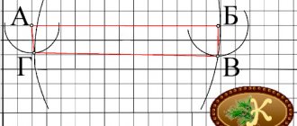
Consideration of this point requires the use of a number of purely technical terms. The boundaries are determined between characteristic corner points relative to the survey reference points. They are scattered over one kilometer square at 2-4 points, coordinated in the GPS system. The difference between the real coordinates of the corner points and the coordinates obtained as a result of engineering measurements is the error.
It is formed as a result of the action:
- Human errors.
- Inaccuracies in the operation of devices.
- Weather features.
- Nuances of the terrain.
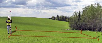
In calculations, the main indicator and starting point of all error measurements is the survey justification point. This point is where the engineer installs the measuring instruments. In this case, uneven landscapes and engineer errors can lead to displacement. The measuring device itself has a certain amount of error. Thus, in order to reduce the magnitude of the error, measurements are made multiple times.
Permissible error: what it depends on
The errors obtained during measurements are influenced by many factors. One of the most important criteria affecting accuracy is the qualifications of the engineer. An important point is the equipment; the more professional and high-quality it is, the more reliable measurements can be taken.
The magnitude of the error depends on:
- qualifications of an executive engineer;
- accuracy of geodetic equipment;
- calculation methods used;
- external factors (territory topography, seasonality, weather conditions at the stage of the procedure).
What affects the accuracy of coordinate determination? Firstly, the human factor. That is why many specialists are now trying to use the most modern devices to reduce this moment to a minimum.
Secondly, these are errors due to the devices themselves. It may happen that even the most accurate land surveyor will be let down by the device.
Any device has a slight effect on measurements due to design features. If they are not digital, then the readings may vary from person to person.
The weather also affects it. It is not surprising that the result obtained during heavy rain or wind will be different from that obtained in good weather.
And finally, the last, and most irremovable reason is the terrain features. The more complex it is, the greater the likelihood that errors will be made.
Even experienced engineers and surveyors admit that when determining boundaries on the same area, different results will be obtained at different times. And the only important thing is that the error ultimately does not exceed the permissible one.
The amount of permissible error will be different for cities and rural areas. So, for the city it will be 10 centimeters, and for suburban areas 20 centimeters will be allowed, and for agricultural land 25 cm is already allowed.
Legislative framework
In addition to technical nuances, the term also has a legal basis, which establishes the amount of permissible error.
This point is regulated:
- 218-FZ (clause 13, article 22);
- letters of the Ministry of Economic Development No. 518 and 582 dated 08.12 and 12.09;
- 90 order of the Ministry of Economic Development.
The latest document defines the calculation formulas for the permissible error, as well as methods for determining corner points and their coordinates:
- Polygonometric.
- Photographic.
- Satellite methods.
- Methods of analysis.
- Taking photographs.
- Cartography.
Characteristic points of the boundaries of the land plot
To determine the location of a land plot, a description of the boundaries of the plot is key.
The location of a site refers to the coordinates of characteristic points of its boundaries, that is, points of change in the description of the boundaries of the site and dividing them into parts (clause 7 of Article 38 of the Federal Law of July 24, 2007 No. 221-FZ “On the State Real Estate Cadastre”). This law loses its force on January 1, 2020, however, a similar definition is contained in the new Federal Law of July 13, 2020 No. 218-FZ “On State Registration of Real Estate.”
With regard to certain parts of the boundaries, regulations may provide for a different procedure for determining their location: by indicating natural or artificially constructed objects, information about which is available in the State Real Estate Cadastre and whose boundaries coincide with the external boundaries of the site.
The procedure, methods and methods for determining the coordinates of characteristic points of the boundaries of a land plot are regulated by Order of the Ministry of Economic Development of the Russian Federation dated August 17, 2012 No. 518.
The basis for establishing characteristic boundaries is the coordinate system established by law for maintaining the state real estate cadastre (GKN). For practical determination of the coordinates of characteristic points, the following methods are used:
- 1) Geodetic method;
- 2) Satellite geodetic measurement method;
- 3) Photogrammetric method;
- 4) Cartometric method;
- 5) Analytical method.
Error limits
The minimum sizes of permissible errors are established at the regional and municipal levels. For the majority of subjects, divergence norms are established based on the purpose of the land:
- Land for individual housing construction - 300 square meters.
- In dacha construction - 600 square meters.
- KFK land – 600 square meters.
- Land of private farms - private household plots - 400 square meters.
- Vegetable garden lands – 400 sq.m.
- For the construction of garages - no more than 18 square meters.
- Land for organizing street trading - no more than 5 sq.m.
At the same time, it should be noted that the norms of permissible error during land surveying also depend on the functional purpose of the land, which consists of the following values:
- Areas within populated areas – up to 10 cm.
- Private household plots – 20 cm.
- Agricultural land – 2.5 m.
- Lands for industrial use – up to 0.5 m.
Basics of geodetic measurements (page 5 of 11)
· satellite geodetic networks of the 1st class (SGS-1).
These three classes of networks are strictly interconnected: FAGS is the support for the VGS, and the VGS is the support for the SGS-1.
When constructing FAGS, VGS and SGS-1, it is planned to link the existing GGS to the highest class of satellite networks, i.e. the existing GGS will be a condensation network.
FAGS points are located at a distance of 800-1000 km, their number is 50 + 70, 10-15 points should be permanent, and the rest should be reassigned in groups at intervals depending on the geodynamic activity of the region.
The spatial position of FAGS points is determined in a general earthly coordinate system with an error in the position of points relative to the center of mass of no more than (2-3)10-8 R, where R is the radius of the Earth, the error in the relative position of FAGS points is no more than 2 cm in plan and 3 cm in height . To ensure this accuracy, it is necessary to use the entire complex of existing space measurements (laser, radio interferometric and others).
The VGS is a system of points with a distance D = 150-300 km between them, which are determined by relative methods of space geodesy with a mean square error of no more than 3 mm + 5 • 10-8 D for plan coordinates and 5 mm + 7 • 10-8 D - for geodetic heights.
SGS-1 consist of a system of easily accessible points with a density sufficient for consumers to use all kinds of satellite definitions. SGS-1 are determined by relative methods of space geodesy with root mean square errors: 3 mm + 10-7 D in plan and 5 mm + + 2 • 10-8 D in geodetic height for geodynamically active regions and 5 mm + 2 • 10-7. D in plan and 7mm + 3 • 10-7 D in height for other regions. The average distance between SGS-1 points is 25-35 km. In economically developed areas, SGS-1 points, depending on consumer requirements, may have a higher density.
Permanent FAGS points are mainly created on the basis of existing satellite (space) observation points, astronomical observatories, Earth rotation service points, radio interferometric complexes with ultra-long-range Quasar bases, the Delta program, etc. At FAGS points, two observation programs are provided: permanent observations of GLONASS and GPS satellite systems (including international programs) and observations of other specialized satellites and space objects in accordance with interdepartmental programs for the construction of the Federal Agency for Civil Aviation Information System.
It should be noted that satellite technologies cannot always be used in solving traditional geodetic problems, for example, the relative accuracy of determinations at short distances is insufficient, the use of GPS methods in precise engineering geodesy is limited, the process of linking landmark points, easily solved in traditional technology, becomes quite complex and expensive, especially in closed areas, in satellite technology, since the volume of satellite determinations in this case more than doubles.
3. Errors in geodetic measurements (theory and problem solving)
3.1 Geodetic measurement, measurement result, measurement methods and conditions. Equal and unequal measurements
Measurement is the process of comparing a certain physical quantity with another quantity of the same name, taken as a unit of measure.
Unit of measure –
the value of a physical quantity adopted for the quantitative assessment of a quantity of the same kind.
The result of measurements is a number equal to the ratio of the measured value to a unit of measure.
The following types of geodetic measurements are distinguished:
1. Linear, as a result of which oblique irrational distances between given points are obtained. For this purpose, tapes, tape measures, wires, optical light and radio range finders are used.
2. Angular, determining the magnitude of horizontal angles. To perform such measurements, theodolite, compasses, and eclimeters are used.
3. Altitude, as a result of which the differences in heights of individual points are obtained. For this purpose, levels, theodolites-tacheometers, and barometers are used.
There are two methods of geodetic measurements: direct and mediocre (indirect).
Direct –
measurements in which the quantities being determined are obtained as a result of direct comparison with a unit of measurement.
Indirect –
measurements in which the determined quantities are obtained as functions of other directly measured quantities.
The measurement process includes:
· Object – properties of which, for example, size, characterize the measurement result.
· Technical means – obtaining results in given units.
· The measurement method is determined by the theory of practical actions and techniques of technical means.
· Performer of measurements – recording device
· The external environment in which the measurement process takes place.
Measurements distinguish between equally accurate
and
unequal
. Equally accurate are the results of measurements of homogeneous quantities, performed using instruments of the same class, using the same method, by the same performer under the same conditions. If at least one of the elements that makes up the set changes, then the measurement result is unequal.
3.2 Classification of geodetic measurement errors. Mean square error. Gauss and Bessel forms for its calculation
Geodetic measurements, carried out even in very good conditions, are accompanied by errors, i.e. deviation of the measurement result L from the true value X of the numbered quantity:
∆ = LX
True is a value of the measured quantity that would ideally reflect the quantitative properties of the object. An unattainable condition—true value—is a hypothetical concept. This is a value that can be approached infinitely close, it is not achievable.
Measurement accuracy is the degree of approximation of its result to the true value. The lower the error, the higher the accuracy .
Absolute error
expressed by the difference between the value obtained as a result of the measurement and the true measurement of the quantity. For example, the true value of l = 100 m, however, when measuring the same line, the result was 100.05 m, then the absolute error is:
E
= X measured – X
E = 100.05 – 100 = 0.05 (m)
To obtain the value, it is enough to make one measurement. It is called necessary, but more often it is not limited to one measurement, but is repeated at least twice. Measurements that are taken beyond what is necessary are called redundant (additional). )
, they are a very important means of monitoring the measurement result.
The absolute error does not give an idea of the accuracy of the result obtained. For example, an error of 0.06 m can be obtained when measuring l = 100 m or l = 1000 m. Therefore, the relative error is calculated:
C
= E avg / X
C = 0.06 / 100 = 1/1667, i.e. at 1667 m of measured l an error of 1 meter is allowed.
Relative error
– the ratio of the absolute error to the true or measured value. Expressed as a fraction. According to the instructions, the terrain line should be measured no rougher than 1/1000.
Errors arising from individual factors are called elementary. The generalized error is the sum of the elementary ones.
There are:
· rough (Q),
· systematic (O),
· random (∆).
Rough
Measurement errors arise as a result of blunders, miscalculations of the performer, his inattention, and undetected malfunctions of technical equipment. Gross errors are completely unacceptable and must be completely eliminated from the measurement results by conducting repeated, additional measurements.
Systematic
measurement errors are a constant component associated with defects: vision, malfunction of technical equipment, temperature. Systematic errors can be either unilateral or variable (periodic errors). They strive, if possible, to take them into account or exclude them from the measurement results when organizing and carrying out work.
Random
Measurement errors inevitably accompany all measurements. Random errors cannot be excluded, but their influence on the desired result can be weakened by carrying out additional measurements. These are the most insidious errors that accompany all measurements. They can be different both in size and sign.
E = Q + O +∆
If gross and systematic errors can be studied and excluded from the measurement result, then random ones can be taken into account based on deep measurements. Study based on probability theory.
In practice, the difficulty lies in the fact that measurements are carried out a limited number of times and therefore, to assess the accuracy of measurements, an approximate estimate of the standard deviation, which is called the root-mean-square error (RMS), is used.
Gauss proposed a formula for the root-mean-square error:
∆2av = (∆21 + ∆22 +… +∆2n) / n,
∆2 = m2 = (∆21 + ∆22 +… +∆2n) / n,
∆ = m,
∆av =
m = √(∑∆2 i / n )
The formula is applied when errors are calculated from true values.
Bessel formula:
m
= √(∑ V 2 i / ( n -1))
The root mean square error of the arithmetic mean is Ön times less than the root mean square error of an individual measurement
M= m / Ö n
When assessing, the mean square error with a weight equal to one is used as a unit of accuracy. It is called the mean square error of a unit of weight.
Error correction issue
The consequences of incorrect definition of boundaries and significant deviations from permissible errors lead to incorrect assessment of taxes, as well as to disputes with neighbors.
For minor errors, there is no need to re-survey.
Thus, discrepancies may arise due to technical or cadastral errors. To make corrections, you simply need to submit an application to the cadastre and cartography authorities, attaching documents reflecting the correct measurements. Naturally, repeated boundary work is carried out to identify and correct errors.
What error is allowed when surveying land plots?
In the first case, surveyors focus on physical objects - pegs, fences, poles, etc.
If the boundaries are along, then the information is adjusted based on the accuracy indicators accepted for this category of land. If the boundaries on the ground (actual boundaries) are determined correctly, then they will coincide with the boundaries according to the cadastre, taking into account the permissible error values.
The cadastral engineer is responsible for calculating the error, clarifying the boundaries and area of the land plot. There are two main options for determining the location of the boundary boundary: Indicators Description If the owner of the land plot has not previously ordered a land surveying procedure, then the boundaries are fixed according to physical marks that exist at the time of entering information (this can be a fence or another) If the land plot has already been demarcated and information about the boundaries is contained in cadastral documents, then to clarify the boundaries, boundaries are drawn on the ground, or boundaries are taken out in nature